
Wireless power for devices that can't be plugged in.
Distributed sensors in industrial, logistics and smart-building deployments rarely have a power budget. AirInduct Sim helps you design coils that extract enough to run them.
Can AirInduct Sim design coils for batteryless IoT sensors?
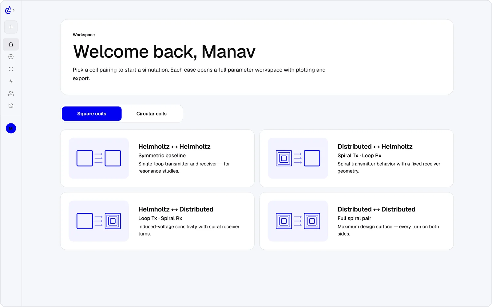
AirInduct Sim can design the coil pair that powers a batteryless IoT sensor, from a compact planar spiral on a PCB to a wound reader coil. Pick a DTC (descending-turn planar spiral) topology for printed coils or a Helmholtz pair for wound ones, set turns, size, gap and frequency — 13.56 MHz for NFC-style links, for instance — and the closed-form solver returns mutual inductance M, coupling k, induced voltage and peak field in seconds. A lateral misalignment sweep shows how much offset the sensor tolerates before coupling drops, and the optimizer searches for a geometry that hits a target inside your footprint. When the design is ready, AirInduct Sim exports a KiCad footprint (.kicad_mod) for the PCB, a DXF outline for the enclosure and a SPICE netlist with L, M and k for the rectifier stage. The model is air-core and magnetostatic, so metal enclosures and ferrite sheets need a FEM check.
Batteryless
Harvest enough to run an ultra-low-power sensor node without any onboard battery. Receiver-side rectifier analysis ships with the simulator.
NFC at 13.56 MHz
ISM-band coil geometries optimised for reader-to-tag coupling at centimetre ranges.
Industrial
Rotating shafts, sealed enclosures — WPT powers sensors where wires fail. Misalignment sweeps quantify the operating envelope.
Mass production
Export to KiCad for direct PCB integration; optimise for minimum trace count and maximum yield via the genetic optimiser.
Power the edge.
Frequently asked questions
What frequency suits batteryless IoT sensors?
13.56 MHz (NFC adjacent) is the most common choice for batteryless IoT and asset-tracking sensors because tags are inexpensive and reader hardware is plentiful. AirInduct simulates 13.56 MHz directly with closed-form Biot–Savart.
Can AirInduct model rotating-shaft or moving-target wireless power?
Partly. Sweep lateral offset and gap to map the coupling envelope as the receiver translates. The coils are modelled coaxial with parallel planes, so angular tilt during rotation is not modelled.
Is this a free alternative to FEM EM simulators for low-power coils?
For air-core coils, yes. AirInduct Sim returns inductance, mutual coupling and 3D field maps for low-power sensor coils in seconds — no licence, no 2D-only restriction, no install — and it is free to start.
Can I export the geometry to KiCad for a printed PCB coil?
Yes — every coil exports to KiCad PCB footprint, DXF outline and a SPICE netlist with L, M and k for downstream board-level simulation.